When computers performs network communication, it’s essentially inter-process communication across operating systems. When communicating between processes within the same operating system, the process exchanges data through pipes, FIFOs, shared memory, etc{1}. The data itself does not change. In network communication, because the operating system is spanned, the process needs to help locate the remote process by using the network layer and transport layer module provided by the operating system. This article briefly describes the data (encapsulation layer) of the interprocess communication when it interacts across the TCP/IP network protocol stack, data encapsulation, transmission and decapsulation.
A Typical TCP/IP Network
The two Ethernet switches form two Ethernet LAN segments (LAN A and LAN B), where the network segment LAN A is 10.22.5.0/24 and the network segment LAN B is 10.16.56.0/24. Segments are connected by a router to form an internet. 
Use VirtualBox and GNS3 to build this topology, involving the operating system and software,
- Host A in network A: Ubuntu14.04
- Host B in Network B: Ubuntu 12.04 (running in Virtualbox)
- Router Router OS: Cisco 2600 (running on GNS3)
TCP/IP protocol stacks
The TCP/IP nprotocol stack is the most widely applied protocols in the network area (Figure 2). In this protocol stack, each layer corresponds to the software associated with this layer. The “application layer” represents the user process and the related protocols that it complies with. For example, when browsing a webpage using a browser, the browser process communicates with the remote web server process, both of which comply with the HTTP protocol, the browser sends the request, and the server sends back the responses. The “transport layer” represents the software modules implemented in the operating system kernel (sometimes not in OS kernel) such as TCP module, UDP module and the protocols it complies with. The transport layer provides services for the upper layer. For example, the application layer needs data not to be lost during transmission, and not duplicated, the application layer needs to reference the TCP protocol to send and receive data. The “network layer” is used to find the destination host for the packets and route the data to the destination host. The “data link layer” performs the actual transceiving operation of the data. Data encapsulation is performed in this protocol stack structure. (In fact, the implementation of the transport layer is not necessarily limited to the system kernel. At present, most operating system implementations implement the transport layer protocol in the kernel.) 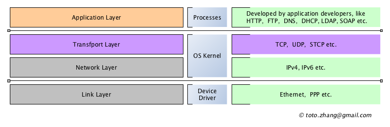
Data from user processes, application layer messages
The application layer protocol is the protocol used for interprocess communication in the internetwork. It is mainly used for two processes or multiple processes in the network to send data back and forth. The data sent at this layer, we call them messages, the message sent between processes, generated by the process developer according to the application layer protocol it refers to, such as HTTP messages, LDAP messages, etc. In order to clearly explain the problem, we temporarily set aside complex and existing application layer protocols to design a minimalist new application layer protocol. The protocol is as follows:
- In an internet.
- Server:Server process running on host S.
- CLient: Client process running on host C.
- Client sends a string “request,hostname”, which is ask for the hostname of the server.
- After the server receives the message, the server get the hostname of itself, and response a string “response, [the real hostname]”。
According to the actual situation of modern multi-task operating system, this process can be shown as follows: 
In TCP/IP networks, the process Client provides the Client OS with information about the process Server (IP address, TCP service port number). Process Server also notifies its operating system, Server OS, on which TCP port it is listening for connection requests. The above content is what application developers and application layer protocol stakeholders (such as network technical support, black hat, white hat packet analysis, etc.) need to pay attention to.
Encapsulation of application-layer messages in Tranport Layer
The request message “request,hostname” initiated by the process “Client” will not be sent to the receiver process “Server” arbitraily. It has to go through the network topology showen in figure 1 to the Server process with the help of the operating system. The details of “message” itself does not provide enough information to the client operating system to locate the remote host in the network, or even the process Server running in the remote host.Therefore, the Client process needs to provide this information to the operating system, and the operating system will append this information to the application layer message data. This process of information appending is called “data encapsulation”.In order to focus on “data encapsulation”, details such as segmentation of the transport layer will not be explained here, and these details will be specifically explained in subsequent articles.
According to the TCP/IP stack structure, the application layer message “request,hostname” first comes to the TCP transport layer processing module in the OS Kernel. The TCP module append the source port to the message to identify which process of ClientOS issued the data from. This port number is temporarily assigned by the operating system. In addition, destination port added to identify the remote process which will be used by server side. This Port number is provided to the operating system kernel by the Client process. In most cases, the so-called “well-known Port” is used. Of course, the choice of Port number is not limited.
Next, the TCP module adds some important additional fields to the message, that is, the part I identified as “misc”, which is some core functional data fields (such as UDP, SCTP, etc.) that distinguish TCP protocol from other transport layer protocols. At this point, the transport layer wraps up the application layer messages, and the data encapsulated by the transport layer is generally referred to as “segment”. 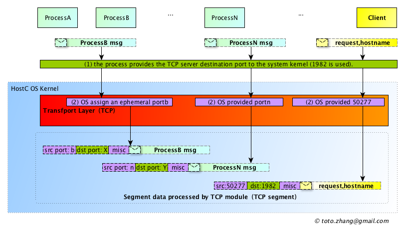
The details of the Misc section are part of TCP’s header structure, which I won’t refer now. 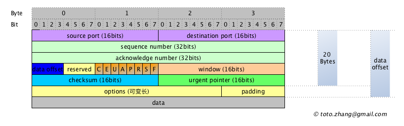
This is what transport layer protocol developers need to pay attention to, what services the protocol provides for the upper layer, such as ensuring that the application layer data is not lost in the transmission.
Encapsulation of segment in Network Layer
After TCP encapsulation, segment data arrives at the network layer. As mentioned, the main function of the network layer is host addressing and routing. The protocol of this layer is to find the remote host in the complex network. So the destination address of the remote host is mandatory, and the source address of the host of the sending end is also mandatory when the data is returned from the remote host. These are IP addresses.
The IP address of the server host needs to be provided by the application layer process of client host, because only the client process knows which host the data it sends to. There is still a problem here, how to determine the source address of the client host? Most computers now have multiple network adapters that connect to multiple Homed networks simultaneously, such as WIFI module, physical network cable interface, SIM card WAN interface, VPN interface, virtual network card and so on. Each class of interface will have an IP address. Which IP address is selected as the source address?
Here is the host C configuration in the topology diagram. 1
2
3
4
5
6
7
8
9$ ifconfig
eth0 Link encap:Ethernet HWaddr 08:00:27:ff:66:a4
inet addr:10.16.56.2 Bcast:10.16.56.255 Mask:255.255.255.0
lo Link encap:Local Loopback
inet addr:127.0.0.1 Mask:255.0.0.0
wlan0 Link encap:Ethernet HWaddr 84:3a:4b:1d:c0:c0
inet addr:192.168.1.104 Bcast:192.168.1.255 Mask:255.255.255.0
wwan0 Link encap:Ethernet HWaddr 4a:b6:38:ec:5c:6d
inet addr:10.18.150.41 Bcast:10.18.150.47 Mask:255.255.255.248
In fact, the IP processing module in the kernel needs to refer to the receiver IP address to decide which sender IP address to use. The destination of data sent by the application process Client is host S, whose IP address is 10.22.5.3. At this time, the IP processing module needs to check the local routing table to confirm which network adapter sends data, so as to further package and encapsulate the data. The kernel routing table of host C where the process Client is located is as follows, referring to the destination IP address 10.22.5.3, so the default routing needs to be selected to send data from eth0. The final source address should be eth0 network adapter address 10.16.56.2, which also explains why the host needs the routing table.
1 | $ route -nv |
After the source host IP address and the destination host IP address are determined, the network layer starts encapsulating segment data from the transport layer. The segment data encapsulated by the IP layer is called IP Packet. 
At this point, the data is packaged in the operating system kernel phase.
The packet leaves the host and enters the network
IP packets can now be sent out. Just as the Courier is required to carry the package to the next station when sending the express, we also need the help of the link layer (including the physical layer) to carry the IP packet to the next router when sending the IP packet. The process by which an IP packet goes from one host containing an IP processing software module to another host containing an IP processing software module is called IP packet Hop. The IP packet hops through to its destination. The Ethernet topology in figure 1 is taken as an example. Eth0, the exit of packet sent by host C to host S is network adapter eth0, so eth0’s MAC address is added as the source MAC address. The destination MAC address of the router is obtained through ARP protocol, and the data is sent to the next hop according to the obtained MAC address.
The ARP protocol is equivalent to the network adapter host C sending a broadcast in its own subnet asking, “which host IP address in the network is 10.16.56.1, please provide the MAC address to 08:00:27:ff:66:a4”. Once the MAC address is obtained, the destination MAC address is saved in the ARP cache list of the kernel and the IP packet is sent to the router. Instead of asking the destination MAC address every time using the ARP protocol, is periodically updated. 
After obtaining the destination MAC address, the link-layer software continues to encapsulate the data from the network layer, and the data encapsulated after the link-layer is generally called “Frame”. 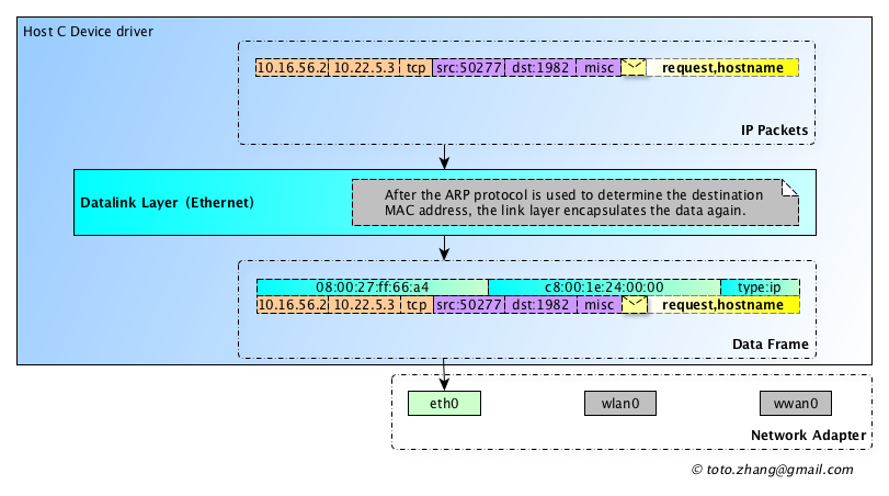
At this point, the frame data can be moved to the physical network card to send out. The physical network card sends this data frame in the form of high and low level through the network cable (1001010101010… ). This data frame first reaches the Switch in the network. When ARP requests the destination MAC address, the Switch has already recorded which two physical ports correspond to the source MAC address and the destination MAC address. Using optical or electrical signals from the physical layer, the switch sends this data frame to the router based on the destination MAC address.
Where packets go, routers come into play
After the data frame to the router, the router first remove all the link layer address information, then reads the destination IP address of the IP layer, and looks up its own routing table, to analyze which interface the network packet should go to , router repeats the processing of the link layer, according to the type of data link, again to attach the data link layer address in IP packet, before encapsulation procedure, the router also using ARP request to get the next-hop link layer MAC address, the data for the next hop. 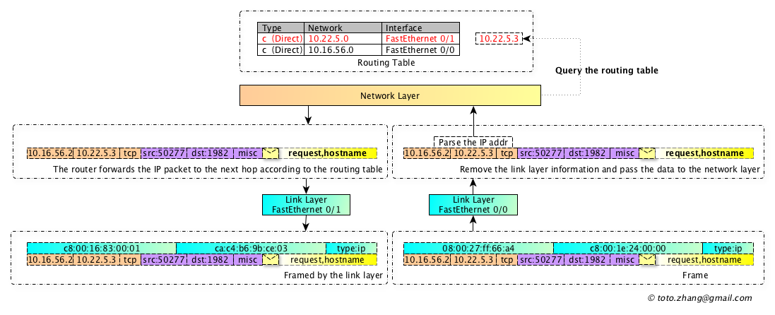
If a packet passes through more than one router, the process is the same, except that the router’s routing table is updated and the number of IP packet hops changes. The above part is the content that router manufacturers pay attention to, such as Cisco, Ericsson, Huawei, etc. Of course, there are also shameless manufacturers secretly steal user data, generally done here quietly.
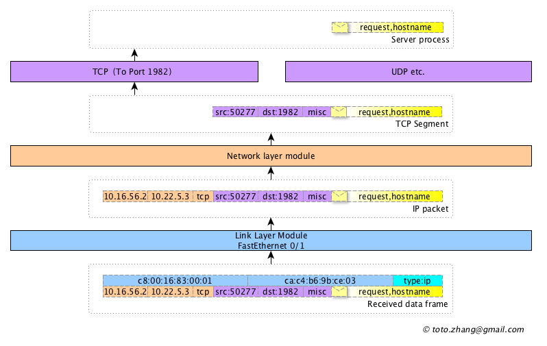
The packet reaches the destination host and decapsulation
- the link layer of the target host removes the relevant fields of the link layer and sends the data to the IP layer processing module according to the type field.
- the IP layer removes the network layer related fields and sends the data to the TCP processing module according to the type field. -tcp layer obtains segment data, removes the fields of this layer, and sends the application message data to the corresponding process Server according to the destination port number.
- finally, the Server process gets the data “request,hostname” in “figure 3”.
When the service process Server gets its own host name and responds to the Client process, the Server repeats the above procedures of encapsulation, sending and decapsulation to return the data to the Client process.